Protean 8x2 Documentation
Click the links below to download images individually or scroll down to see them in their entirety.


Selecting Your FETs:
When selecting FETs, theres more to consider than the voltage and current ratings. How much power a FET can output is limited by how much power the FET itself can dissipate. Fortunately, this isnt difficult to determine for simple low frequency applications.
Key variables to consider form the datasheet:
- VDS Drain-to-Source Voltage, the maximum voltage at which a FET will operate. (The voltage between PWR and Source on the Protean 8x2 board.)
- VGS Gate-to-Source Voltage, the maximum voltage at which a FETs gate will operate. (The voltage between VGS and Source on the Protean 8x2 board.)
- RDS(on) on resistance of the FET given a known VGS value.
- TJ Operating Junction Temperature, (particularly the high/maximum number presented)
- RθJA, (or RthJA) Maximum Junction-to-Ambient temperature in °C per watt of dissipated power.
First, find your loads current requirements at a given voltage, (the voltage of your main power supply), if you dont already know. Measure its current with a multimeter or calculate it using Ohms Law. This will be your drain current, or ID.
Second, determine your RDS(on) value based on your desired or applicable VGS voltage. You may want to increase this value by about 10% or more to account for error.
Third, calculate how much power your FET will dissipate, PD, as if it were a resistor:
PD = ( RDS(on) * 1.1 ) * ID2
So, if we have an RDS(on) of 0.015 ohms at a VGS of 10V, and our load requires 5 amps, our FET would dissipate:
PD = ( 0.015ohm * 1.1 ) * 52
PD = 0.0165ohm * 25
PD = 0.4125 watts
Now we must ask, how hot will the FET get when dissipating this many watts, (PD)? Keep in mind that power, temperature, RDS(on) resistance, and drain current will effect one another. Nearby FETs in operation will also increase ambient temperature. In truth, unless youre using FETs well within specifications, testing will best determine how your FETs will perform. But for estimation, lets calculate how hot a FET will get, TJ, with a given ambient temperature, TA, of 25°C (which is 77°F) plus 10% to account for things getting warm:
TJ = RθJA * PD + 25°C * 1.1
So, if we have an RθJA of 62°C/W and were dissipating 0.41 watts, the FETs temperature would be:
TJ = 62°C/W * 0.41W + 25°C * 1.1
TJ = 25.42°C + 27.5°C
TJ = 53°C
Thats about half the temperature needed to boil water. Not bad. But what if we want to know how much current our FET can handle without being cooled by a heat sink? Firstly we know it cannot exceed the maximum junction temperature of TJ. Assuming an ambient temperature of 25°C + 10%, we can calculate about how much power it can dissipate up to that max TJ:
PD = ( max TJ 25°C * 1.1 ) / RθJA
So, if we have a max TJ of 175°C and a RθJA of 62°C/W, the maximum power the FET can dissipate is about:
PD = ( 175°C 25°C * 1.1 ) / 62°C/W
PD = ( 175°C 27.5°C ) / 62°C/W
PD = 147.5°C / 62°C/W
PD = 2.38 watts
How many amps is that? We use the same formula for power dissipation, PD, but solve for ID, the load current:
PD = ( ( RDS(on) * 1.1 ) * ID2 )
PD / ( RDS(on) * 1.1 ) = ID2
√( PD / ( RDS(on) * 1.1 ) ) = ID
So:
ID = √( 2.38 watts / 0.0165ohm )
ID = √( 144.24 )
ID = 12 amps
However, at 175°C, not only is it well above the boiling point of water, but will cause the RDS(on) resistance to increase, which will increase the power dissipation, which will increase the temperature, etc. This causes thermal runaway and will likely end the life of your FET prematurely. This is why its important to choose the right FET for your application and test!
Additionally, check out some of these video tutorials already available for more information on choosing FETs and how they work:
https://youtu.be/ND8uJWlOgIQ
https://youtu.be/GrvvkYTW_0k
https://youtu.be/SUDkhG9X00s?list=PLjzGSu1yGFjUgTVkhb4WslOVDNAZ3K4yR
PWR LEDs:
If youre using one power source, simply place an LED on the top or the bottom. The K indicates the LEDs cathode, but assumes P-channel FETs on top and N-channel FETs on bottom. Just make sure the cathode is on the negative/ground side or that the anode is on the positive side. The resistor will be on the other side, and its resistance is calculated by:
R = ( Vpower source VLED ) / ILED
So an LED with a voltage drop of 2.1V at only about 5ma of current will require a resistor value of:
R = ( Vpower source 2.1V ) / 0.005A
If our power supply is 48V, our resistor value is:
R = ( 48V 2.1V ) / 0.005A
R = 45.9V / 0.005A
R = 9,180ohms
So we need a 10k resistor which will actually give us 4.6ma of current. So why not use a 2.7k resistor for 17.1ma of current for the LED? Well, we could, but the resistor would need to be rated for 1 watt to dissipate about 0.8 watts of power rather than just under 1/4 watt, which is the typical power rating for your most common axial-lead resistors. Power dissipated by the resistor, PD, is calculated using Ohms Law:
PD = Vdrop2 / R
Here is a table showing some resistor details for LEDs down to 2.1V with some common supply voltages:
| Voltage | Resistor Value | Resistor Power (W) | LED Current |
| 12V | 560 | 0.184 | 18.1ma |
| 24V | 2.7k | 0.183 | 8.2ma |
| 36V | 5.6k | 0.209 | 6.1ma |
| 48V | 10k | 0.214 | 4.6ma |
| 60V | 8.2k | 0.413 | 7.1ma |
| 72V | 12k | 0.411 | 5.9ma |
| 96V | 22k | 0.404 | 4.3ma |
| 120V | 18k | 0.777 | 6.6ma |
| 180V | 39k | 0.815 | 4.6ma |
| 240V | 39k | 1.451 | 6.1ma |
| 240V | 68k | 0.835 | 3.5ma |
Isolated Inputs:
When configured as an input, OptoGND must be set with JP2 or JP1. If N-channel FETs are present, set JP2 to connect OptoGND to the common low/ground side on N-ch FETs. If only P-channel FETs are present, set JP1 to connect OptoGND to the common low/ground side of loads.
Isolated Input Method 1:
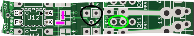
Optocoupler is horizontally flipped and mounted on underside side.
Isolated Input Method 2:
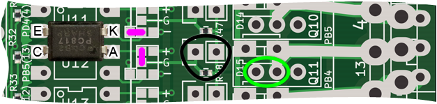
Optocoupler is rotated 180 degrees on top, straddling across two channels.
With this configuration, the channel above must be configured the same way or remain unused as a FET output. The top-most channel remains unaffected and the cathode will already be connected to ground as indicated by the silkscreen.
Isolated Input Resistors:
If the nearby FETs of the nearest 8 channels are N-channel, (i.e. the Source is ground), the resistor circled in black doesnt need to be changed. A resistor will be needed on the pads circled in green though, and its value and power rating can be the same as that needed for the PWR LEDs depending on your positive input voltage. Your input voltage on the main channel pin can be either your main power supply or your +Vgs power supply, (if youre using a separate supply). When the optocoupler is on, you will read a low signal on the logic side as you would a pressed button and a pullup.
However, if the nearby FETs of the nearest 8 channels are P-channel, (i.e. the Source is positive), you have two options:
1. Remove the surface mount resistor circled in black and add a resistor on the pads circled in green as you would for the optocouplers near N-channel FETs, (as previously described above).
2. Use a resistor on the pads circled in black. Its value and power rating can be the same as that needed for the PWR LEDs and will turn on the optocoupler. It will essentially serve as a pullup resistor. Jump the pads circled in green with a wire or solder bridge. Driving the main channel pin low will yield a high on the logic side as an unpressed button and a pullup.

© 2017 Adam L. Humphreys
This work is licensed under a Creative Commons Attribution 4.0 International Public License (CC BY 4.0).